

Company Blogs
I. Four Key Steps in Cooling System Design
1. Calculate the Heat Load First, Then Determine Water Flow
Cooling design is not simply "drilling a few more holes." The first step is to calculate the heat that must be removed based on the plastic's specific heat, melt temperature, ejection temperature, cycle time, and production volume, then convert that into cooling water flow rate. In practice, the cooling water temperature rise is typically controlled at 3–5°C, which determines the flow rate and pipe diameter for each circuit. Common water line diameters are 8–12 mm, and large molds may use 14–16 mm.
2. Water Line Layout: Uniformity First
·Spacing and distance: Center-to-center spacing of water lines is generally 3–5 times the hole diameter, and the distance to the cavity surface is about 1–1.5 times the hole diameter (typically 10–15 mm), ensuring uniform cooling and avoiding local overcooling.
·Follow the hot spots: Areas near the gate, thick walls, and the bottom of deep cavities are heat-concentrated zones and should have denser water lines or dedicated circuits.
·Series vs. parallel: Parts with simple geometry and uniform cooling requirements can be connected in series; when temperature differences between zones must be tightly controlled, use parallel or independent circuits to avoid excessive temperature variation between upstream and downstream sections.
·Inlet/outlet direction: Let water enter from low-temperature zones and exit from high-temperature zones, or use a counter-flow arrangement to minimize temperature variation along the path.
·Clearance from other features: Maintain sufficient wall thickness (generally ≥3–5 mm) between water lines and ejector pins, inserts, and screw holes to prevent leakage and stress concentration.
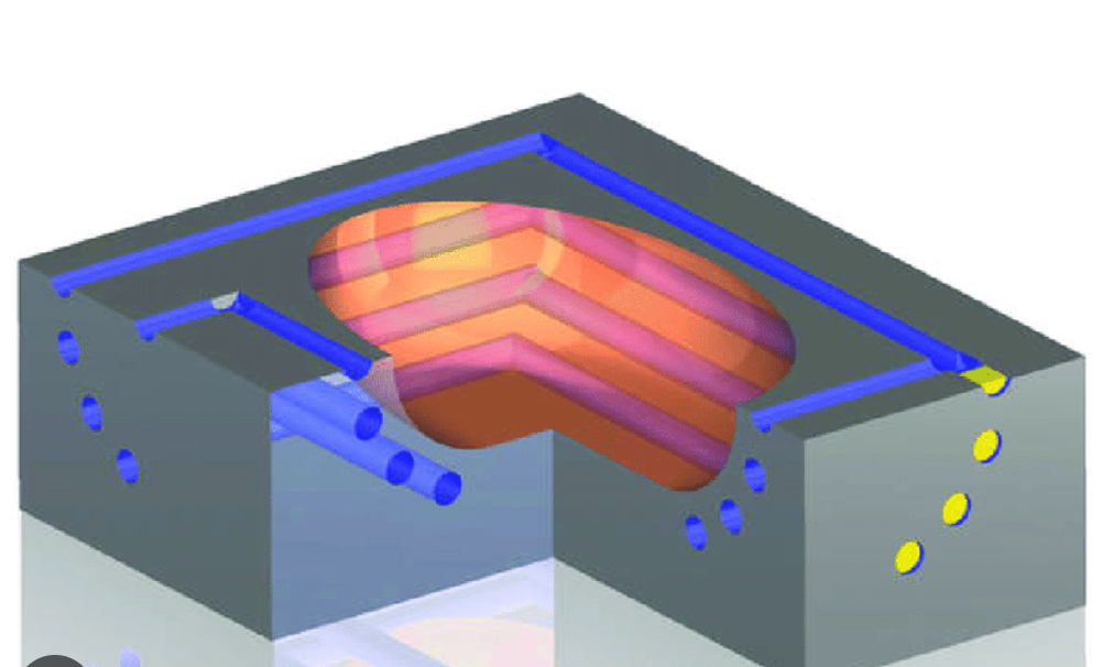
3. Circuit Separation and Temperature Control
The moving half and fixed half are usually temperature-controlled separately, with the fixed half typically set slightly higher. Deep cavities, sliders, lifters, and similar features should have independent circuits. When necessary, use a temperature controller (TCU) to control specific circuits individually for precise thermal management.
4. Materials, Sealing, and Leak Testing
Apply anti-corrosion treatment to water line interiors (stainless steel inserts, plating, etc.), use standard quick-disconnect fittings, and seal with O-rings. A pressure-hold leak test before trial runs is essential — it is the last line of defense against many on-site problems.
II. When Is a Water Well Needed?
A "water well" refers to a deep hole drilled into the mold with a baffle or bubbler inserted, allowing cooling water to reach deep areas and then return. It is used in regions that conventional cross-drilled water lines cannot reach. The following situations typically call for water wells:
·Deep cavities and tall cores: When the core is tall and cross-drilling cannot reach the center or bottom, drill a deep hole from the bottom and install a water well to bring cooling water close to the top of the core.
·Slender cores and small-diameter inserts: When there is insufficient space for cross-drilled circuits, drill axially and use a bubbler for cooling.
·Local hot spots and thick sections: At heat-concentrated areas such as near the gate or thick bosses, where cross-drilled lines are too far away to provide adequate cooling, use a water well aimed directly at the hot spot.
Sliders, lifters, and small inserts: These components are small and geometrically constrained, so water wells or bubbler-type cooling are often used.
·Cross-drilled lines interfering with other features: When a cross-drilled line cannot pass through ejector pins or screws, use a longitudinal deep-hole water well to route around the interference.
·Point cooling for critical areas: For regions sensitive to warpage or requiring rapid local solidification, use a water well for targeted "point cooling."
·Water well design guidelines: Deep hole diameter is typically 8–12 mm; the baffle should leave a gap with the hole wall to form an annular return flow; the bubbler outlet should be 3–5 mm from the hole bottom; for large depth-to-diameter ratios, pay attention to flow resistance and venting; maintain sufficient wall thickness between multiple water wells to prevent cross-talk.
II. Summary
The core logic of cooling system design is straightforward: use cross-drilled circuits in conventional areas to ensure uniform cooling, and add water wells for targeted cooling in deep cavities, slender cores, sliders, and hot spots that cross-drilled lines cannot reach or where heat is heavily concentrated.
In actual projects, we recommend validating the temperature distribution with mold flow analysis (cooling analysis) before finalizing the water line design, then fine-tuning based on measured mold temperatures during trial runs. When cooling is done well, cycle time, warpage, and yield often improve together — making it the single highest-return investment in mold design.
With 20 years of experience in professional mold manufacturing, Haina Mould brings expert analysis to every mold structure. If you need mold manufacturing or project development support, please contact Haina.
Start Your Project Now
📧 Email: ciky@hainamould.com
🌐 Website: https://www.hainamould.com/Contactus/SendMessage
👉 Submit Your Drawings for a Free Technical Evaluation and Quote
(Please upload your 3D/2D drawings, material specifications, estimated quantity, and delivery requirements. We will respond within 24 hours.)

0086 0755 23170739
0086-0755-24325235
ciky@hainamould.com
Room 1605, 16th Floor, Hongyu Building, No. 495, Donghuan 2nd Road, Longhua Subdistrict, Longhua District, Shenzhen, Gongdong ,China 518109


Copyright 2026 Hainamould.com All rights reserved.
-
 0086 0755 23170739
-
 Facebook
-
 WhatsApp
-
 LinkedIn
-
 TOP